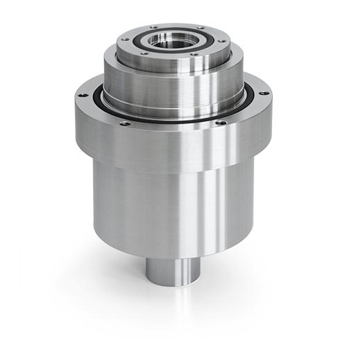
Rotary feedthroughs for very high axial loads, with ALMA flange and short hollow shaft
For very high axial loads
For high transmittable torque
Large internal diameter of hollow shaft
A wide variety of connection options
These rotary feedthroughs are much more than just "hollow-shaft seals". They perform important support and load-bearing functions within the assembly. In conventional solutions the shaft was often installed by the customer. Here the hollow shaft is integrated, not only allowing one sealing position to be omitted, but also ruling out damage during assembly.
The ALMA flange has a highly flexible mounting geometry for both the substrate carrier on the vacuum side and the drive design on the atmospheric side.
Technical data
Leakage rate: < 1 x 10⁻⁸ mbar x l/sOperating temp., non-cooled: -20 bis 60 °C
Operating temperature, cooled: > 60 °C
Rotational speed: up to 300 rpm
Torque: up to 1,200 Nm
Pressure differential: up to 1 bar
Vacuum range: up to UHV
Shaft diameter: up to 130 mm
Flange diameter: up to 198 mm
Radial load: up to 500 N
Axial load: up to 10,000 N
Housing: Stainless steel
Shaft: Stainless steel, magnetic
Magnetic fluid: Maintenance-free
Available options
- Housing cooling
- Customer-specific versions


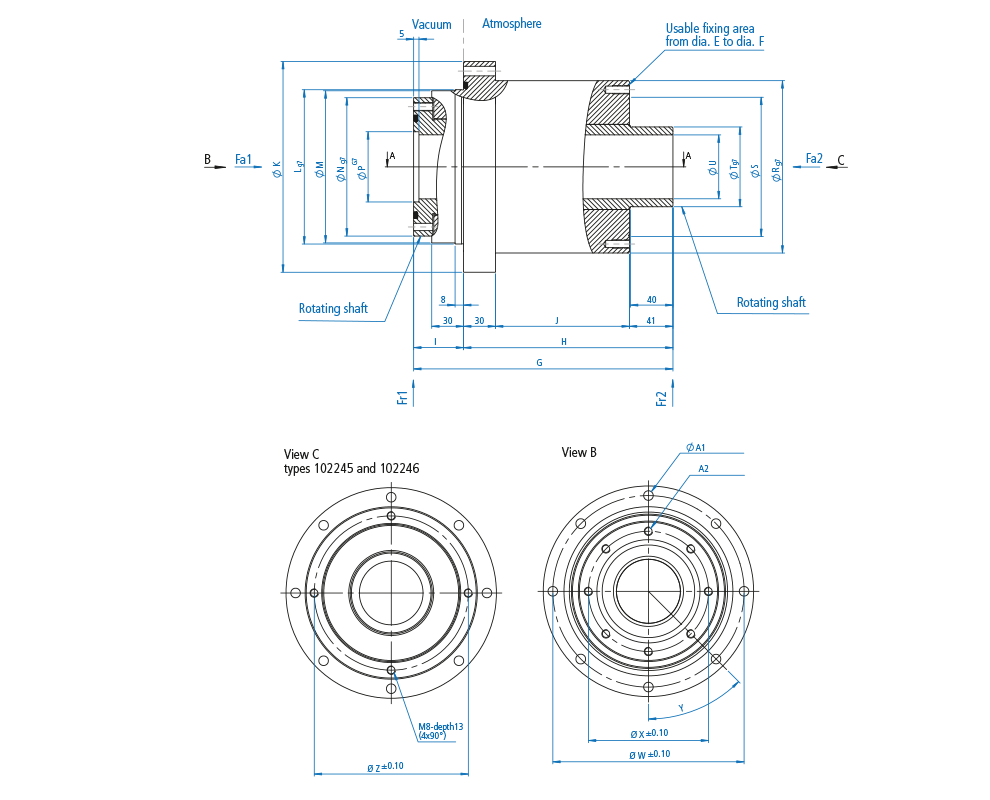
| Model | ALMA-H-AF-030-A-U | |||
|---|---|---|---|---|
| Part number | 1022755 | |||
| Weight (kg) | 10.500 | |||
| Dimensions (mm) | ||||
| Internal diameter, hollow shaft [U] | 30.0 | |||
| Shaft diameter, vacuum side [Ng7] | 80.0 | |||
| Shaft diameter, atmospheric side [Tg7] | 40.0 | |||
| Internal dia. of the shaft fit, vacuum side [pG7] | 36.0 | |||
| Total length [G] | 180.0 | |||
| Length, atmospheric side [H] | 140.0 | |||
| Length, vacuum side [I] | 40.0 | |||
| Total housing length [J+60.0] | 129.0 | |||
| Housing length, vacuum side [J] | 69.0 | |||
| Housing fit diameter, vacuum side [Lg7] | 100.0 | |||
| Housing diameter, vacuum side [M] | 98.0 | |||
| Housing diameter, atmospheric side [Rg7] | 116.0 | |||
| Flange diameter [K] | 140.0 | |||
| Flange length [F] | 30.0 | |||
| Shaft nut diameter [S] | 91.0 | |||
| O-ring diameter [A] | 57.0 | |||
| O-ring diameter [D] | 114.0 | |||
| Available mounting surface [E] | 91.0 | |||
| Available mounting surface [F] | 116.0 | |||
| Pitch circle diameter [W] | 128±0,10 | |||
| Pitch circle diameter [X] | 68±0,10 | |||
| Pitch circle diameter [Z] | 103,0±0,10 | |||
| Through-hole (Ø) [A1] | 7 (6x) | |||
| Tapped hole (Ø x T) [A2] | M6 x 11 (6x) | |||
| Shaft specification | ||||
| Max. rotational speed | 300 min-1 | |||
| Max. transmittable torque* | 200.00 Nm | |||
| Friction torque | 3 Nm | |||
| Max. axial load [Fa1]** | 3.000 N | |||
| Max. axial load [Fa2]** | 3.000 N | |||
| Max. radial load [Fr1]** | 500 N | |||
| Max. radial load [Fr2]** | 500 N | |||
| ALMA-H-AF-045-A-U | ||||
|---|---|---|---|---|
| 1022446 | ||||
| 18.000 | ||||
| 45.0 | ||||
| 110.0 | ||||
| 55.0 | ||||
| 51.0 | ||||
| 212.0 | ||||
| 168.0 | ||||
| 44.0 | ||||
| 157.0 | ||||
| 97.0 | ||||
| 125.0 | ||||
| 123.0 | ||||
| 142.0 | ||||
| 178.0 | ||||
| 30.0 | ||||
| 116.0 | ||||
| 82.0 | ||||
| 139.0 | ||||
| 116.0 | ||||
| 142.0 | ||||
| 160±0,10 | ||||
| 95±0,10 | ||||
| 128,0±0,10 | ||||
| 9 (8x) | ||||
| M8 x 15 (8x) | ||||
| 300 min-1 | ||||
| 450.00 Nm | ||||
| 4 Nm | ||||
| 7.000 N | ||||
| 7.000 N | ||||
| 500 N | ||||
| 500 N | ||||
| ALMA-H-AF-060-A-U | ||||
|---|---|---|---|---|
| 1022445 | ||||
| 27.000 | ||||
| 60.0 | ||||
| 130.0 | ||||
| 75.0 | ||||
| 66.0 | ||||
| 244.0 | ||||
| 197.0 | ||||
| 47.0 | ||||
| 186.0 | ||||
| 126.0 | ||||
| 145.0 | ||||
| 143.0 | ||||
| 162.0 | ||||
| 198.0 | ||||
| 30.0 | ||||
| 131.0 | ||||
| 97.0 | ||||
| 159.0 | ||||
| 131.0 | ||||
| 162.0 | ||||
| 180±0,10 | ||||
| 113±0,10 | ||||
| 145±0,10 | ||||
| 9 (8x) | ||||
| M8 x 18 (8x) | ||||
| 300 min-1 | ||||
| 1.200,00 Nm | ||||
| 8 Nm | ||||
| 10.000 N | ||||
| 10.000 N | ||||
| 500 N | ||||
| 500 N | ||||
* The torque calculation is based on mean calculated values.
** The load calculation is based on assumed values, which cover 95 % of applications.
Individual calculations can be made for borderline applications.
** The load calculation is based on assumed values, which cover 95 % of applications.
Individual calculations can be made for borderline applications.


