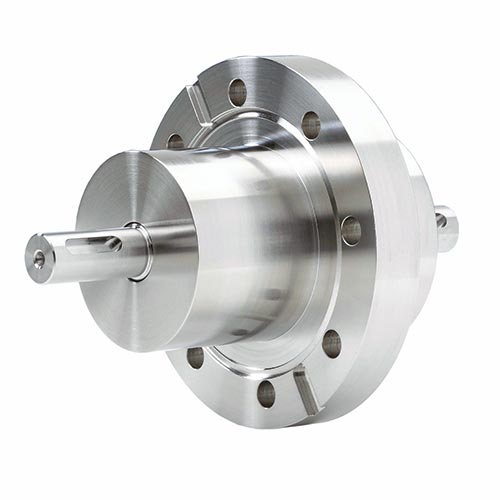
Rotary feedthroughs with CF flange
These rotary feedthroughs can be easily adapted to suit their recipients using the CF flange. The corresponding CF copper gasket is included and also available as a spare part.
The shaft is connected using parallel keys.
The shaft is connected using parallel keys.
Technical data
Leakage rate: < 1 x 10⁻⁸ mbar x l/sOperating temp., non-cooled: -20 bis 90 °C
Operating temperature, cooled: > 90 °C
Rotational speed: up to 10,000 rpm
Torque: up to 32 Nm
Pressure differential: up to 1 bar
Vacuum range: up to UHV
Shaft diameter: up to 15 mm
Flange diameter: up to 63 mm
Radial load: up to 200 N
Axial load: up to 150 N
Housing: Stainless steel
Shaft: Stainless steel, magnetic
Magnetic fluid: Maintenance-free
Available options
- Housing cooling
- Customer-specific versions


| Model | ALMA-M-CF-010-V-U | |||
|---|---|---|---|---|
| Part number | 1020627 | |||
| Weight (kg) | 0.700 | |||
| Dimensions (mm) | ||||
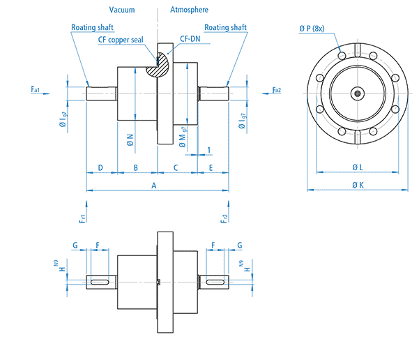
| Shaft diameter, vacuum side [lg7] | 10.0 | |||
| Shaft diameter, atmospheric side [lg7] | 10.0 | |||
| Shaft length, vacuum side [D] | 30.0 | |||
| Shaft length, atmospheric side [E] | 27.0 | |||
| Total length [A] | 115.0 | |||
| Length, atmospheric side [C+E] | 73.0 | |||
| Length, vacuum side [B+D] | 42.0 | |||
| Total housing length [B+C] | 58.0 | |||
| Housing length, vacuum side [B] | 12.0 | |||
| Housing length, atmospheric side [C] | 42.0 | |||
| Housing diameter, vacuum side [N] | 30.0 | |||
| Housing diameter, atmospheric side [Mg7] | 46.0 | |||
| Length of parallel-key groove [F] | 17.0 | |||
| Distance from parallel-key groove to shaft end [G] | 4.0 | |||
| Width of parallel-key groove [HN9] | 3.0 | |||
| Flange | CF-DN 40 | |||
| Flange diameter [K] | 69.5 | |||
| Pitch circle diameter [L] | 58.7 | |||
| Through-hole (Ø) [P] | 6.6 (6x) | |||
| Shaft specification | ||||
| Max. rotational speed | 10,000 min-1 | |||
| Max. transmittable torque* | 9.00 Nm | |||
| Friction torque | 0.3 Nm | |||
| Max. axial load [Fa1]** | 50 N | |||
| Max. axial load [Fa2]** | 50 N | |||
| Max. radial load [Fr1]** | 75 N | |||
| Max. radial load [Fr2]** | 75 N | |||
| ALMA-M-CF-015-V-U | ||||
|---|---|---|---|---|
| 1020180 | ||||
| 2.250 | ||||
| 15.0 | ||||
| 15.0 | ||||
| 35.0 | ||||
| 35.0 | ||||
| 160.0 | ||||
| 80.0 | ||||
| 80.0 | ||||
| 90.0 | ||||
| 45.0 | ||||
| 45.0 | ||||
| 60.0 | ||||
| 70.0 | ||||
| 20.0 | ||||
| 5.0 | ||||
| 5.0 | ||||
| CF-DN 63 | ||||
| 113.5 | ||||
| 92.1 | ||||
| 8.4 (8x) | ||||
| 9,000 min-1 | ||||
| 32.00 Nm | ||||
| 0.4 Nm | ||||
| 150 N | ||||
| 150 N | ||||
| 200 N | ||||
| 200 N | ||||
* The torque calculation is based on mean calculated values.
** The load calculation is based on assumed values, which cover 95 % of applications.
Individual calculations can be made for borderline applications.
** The load calculation is based on assumed values, which cover 95 % of applications.
Individual calculations can be made for borderline applications.


