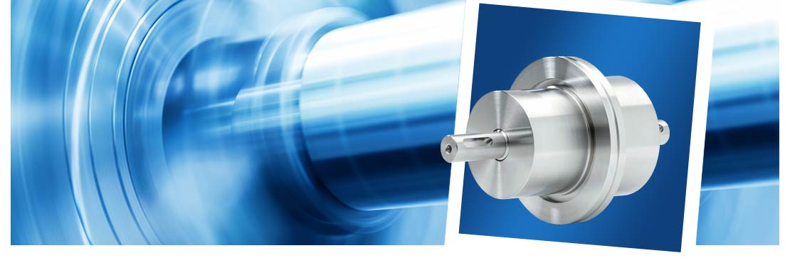
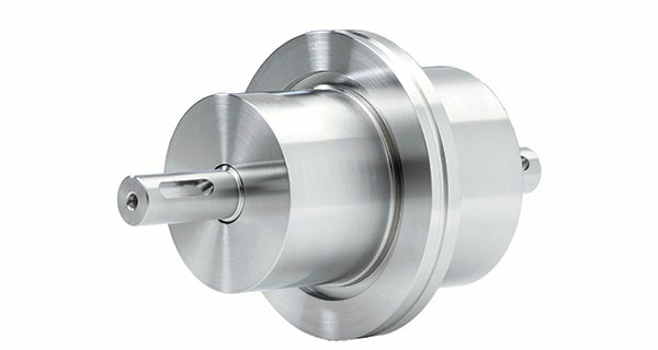
Rotary feedthrough with ISO-K flange
This standard rotary feedthrough is designed to be mounted on an ISO-K flange and is available ex stock. The shaft is connected using parallel keys.
Operating temp., non-cooled: -20 bis 90 °C
Operating temperature, cooled: > 90 °C
Pressure differential: up to 1 bar
Vacuum range: up to UHV
Housing: Stainless steel
Shaft: Stainless steel, magnetic
Magnetic fluid: Maintenance-free
Technical data
Leakage rate: < 1 x 10⁻⁸ mbar x l/sOperating temp., non-cooled: -20 bis 90 °C
Operating temperature, cooled: > 90 °C
Pressure differential: up to 1 bar
Vacuum range: up to UHV
Housing: Stainless steel
Shaft: Stainless steel, magnetic
Magnetic fluid: Maintenance-free
Available options
- Housing cooling
- Customer-specific versions
| Model | ALMA-M-ISO-K-015-V-U | |||
|---|---|---|---|---|
| Part number | 1020628 | |||
| Weight (kg) | 2.400 | |||
| Dimensions (mm) | ||||
| Shaft diameter, vacuum side | 15g7 | |||
| Shaft diameter, atmospheric side | 15g7 | |||
| Shaft length, vacuum side | 35.0 | |||
| Shaft length, atmospheric side | 35.0 | |||
| Total length | 160.0 | |||
| Length, atmospheric side | 85.0 | |||
| Length, vacuum side | 75.0 | |||
| Total housing length | 90.0 | |||
| Housing length, vacuum side | 40.0 | |||
| Housing length, atmospheric side | 50.0 | |||
| Housing diameter, vacuum side | 60.0 | |||
| Housing diameter, atmospheric side | 70g7 | |||
| Length of parallel-key groove | 20.0 | |||
| Distance from parallel-key groove to shaft end | 5.0 | |||
| Width of parallel-key groove | 5N9 | |||
| Flange diameter | ISO-K DN63 | |||
| Shaft specification | ||||
| Max. rotational speed | 9,000 min-1 | |||
| Max. transmittable torque* | 32.00 Nm | |||
| Friction torque | 0.4 Nm | |||
| Max. axial load [Fa1]** | 150 N | |||
| Max. axial load [Fa2]** | 150 N | |||
| Max. radial load [Fr1]** | 200 N | |||
| Max. radial load [Fr2]** | 200 N | |||
* The torque calculation is based on mean calculated values.
** The load calculation is based on assumed values, which cover 95 % of applications.
Individual calculations can be made for borderline applications.
** The load calculation is based on assumed values, which cover 95 % of applications.
Individual calculations can be made for borderline applications.

")